| Brief Description | |
|---|---|
|
File:
\examples\Processing\Geometry\ScalingLine\ScalingLineP16.va |
 |
|
Default Platform: mE5-MA-VCL |
|
|
Short Description Scaling and transformation of a line scan image |
|
The VisualApplets designs "ScalingLineP8.va“ and “ScalingLineP16.va” scale an image of a grayscale line scan camera in CameraLink Full configuration by an arbitrary factor to transform the width of an image between the input and the output. „ScalingLineP8.va“ is designed for a parallelism of 8 and “ScalingLineP16.va” for a parallelism of 16 for a marathon VCL platform. This document describes the algorithm and implementation in VisualApplets. For usage of the design, a number of lookup table values need to be calculated. An included C++ and Matlab program provide these calculations to simplify the usage.
The scaling/transformation/distortion correction of a line image is performed on the basis of source and target image coordinates. In the following the basic principle of the algorithm is explained with example coordinate pairs and parallelism 4.
Target coordinates: 0 1 2 3 | 4 5 6 7 | 8 9 10 11 | 12 13
14 15
Source coordinates: 0.3 0.5 1.4 1.5 | 2.2 3.4 3.6 4.2| 5.4 5.5 7.8 8.5 | 9.1 11.4 13.3 14.1
We use the Target-To-Source procedure. For every pixel in the target image (= output image to PC) we select the corresponding (rounded off) integer coordinate and the corresponding pixel value in the source image. Positions between pixels are considered by selecting also the preceding pixel neighbor of the current pixel coordinate in the source image. With linear interpolation the correct pixel value in the output image is calculated. Due to parallelism single pixels can not be read from source image. Therefore “words” (unities of pixels read at the same time) have to be read in a useful sequence. It may happen that words have to be read more than once or never. Within these words, which have been read from the source image, the correct pixel positions for the creation of the output word have to be selected. Pixels not needed from the words read are deleted. The following example illustrates the read access from source image coordinates:
| Memory Read Count cycles | Requested Target Coordinates | Respective Source Coordinates | Read Word/ incl. Pixel | Use Pixel in Word |
|---|---|---|---|---|
| 1 | 0, 1 2, 3 | 0.3, 0.5, 1.4, 1.5 | 0/ 0, 1, 2, 3 | 1, 1, 2, 2 |
| 2 | 4 | 2.2 | 0/ 0, 1, 2, 3 | 3, x, x, x |
| 3 | 5, 6, 7, 8 | 3.4, 3.6, 4.2, 5.4 | 1/ 4, 5, 6, 7 | 4, 4, 5, 6 |
| 4 | 9 | 5.5 | 1/ 4, 5, 6, 7 | 6, x, x, x |
| 5 | 10, 11, 12 | 7.8, 8.5, 9.1 | 2/ 8, 9, 10, 11 | 9, 8, 10, x |
| 6 | 13, 14, 15 | 11.4, 13.3, 14.1 | 3 / 12, 13, 14, 15 | 12, 14, 15, x |
Table 24. Reading Cycles
While “x” indicates that the pixel is deleted.
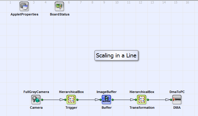
The main components of the design are (Fig. 333):
1. Interface to line scan camera including trigger system and buffer;
2. Scaling of camera image (in Transformation);
3. DMA data transfer to PC;

In the following we will describe the main component Transformation in detail.
You can see the components of Transformation in Fig. 334.
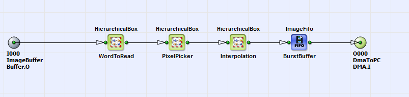
The scaling of a camera line scan image is operated in Target-To-Source procedure. In WordToRead we select in which useful order the unities of 8 parallelism 8 in „ScalingLineP8.va“) or 16 (parallelism 16 in „ScalingLineP16.va“) pixels (= ”word”) are read from input camera image. In PixelPicker we decide which pixels we need from the words read. Interpolation considers for the calculation of the pixel values in the output image the interpixel position in the source image.
The components of the module WordToRead are shown in Fig. 335.
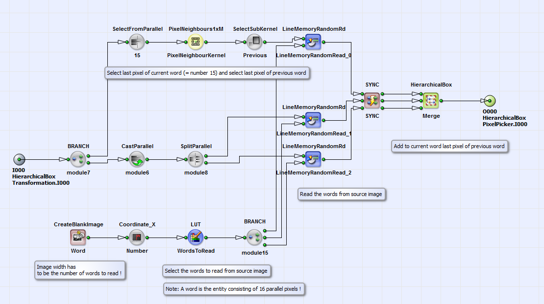
The order and frequency of the words to be read from the source image is defined in LUT: WordsToRead. The content of this table is created with the external C++ program „ScalingLUTS.cpp” or alternative with the MATLAB modules “LUTS_Scaling.m” and “ScalingTablelLine.m”. See therefor section in this document. The input link for this lookup table is defined with CreateBlankImage and Coordinate_X. The value of parameter ImageWidth of CreateBlankImage has to be exactly the same as the number of elements in LUT: WordsToRead. The parameter ImageHeight has to match the image dimensions of the source image in y-direction. The words from the source image are read from buffers LineMemoryRandomRd_1 and LineMemoryRandomRd_2 in an order defined by LUT: WordsToRead. The source image is linearly written to these buffers. Here two buffers are necessary due to a maximum bit depth of 64 bit and parallelism 1. For every word the last pixel of the preceding word is selected and read (upper operation line before SYNC). This value is added to the corresponding word with the operator Merge.
In the module PixelPicker (see Fig. 336) the pixels for the scaled output words are selected with the components Pick_0 to Pick_15 (or to Pick_7 with parallelism 8) from the words read. If pixels of a word read are not needed (see section ) the lookup table RemovePixel deletes them. The content of the tables named above (Pick_0 to Pick_15 and RemovePixel) can be created with the external C++ program „ScalingLUTS.cpp” or alternative with the MATLAB modules “LUTS_Scaling.m” and “ScalingTablelLine.m”. See therefor also section in this document.
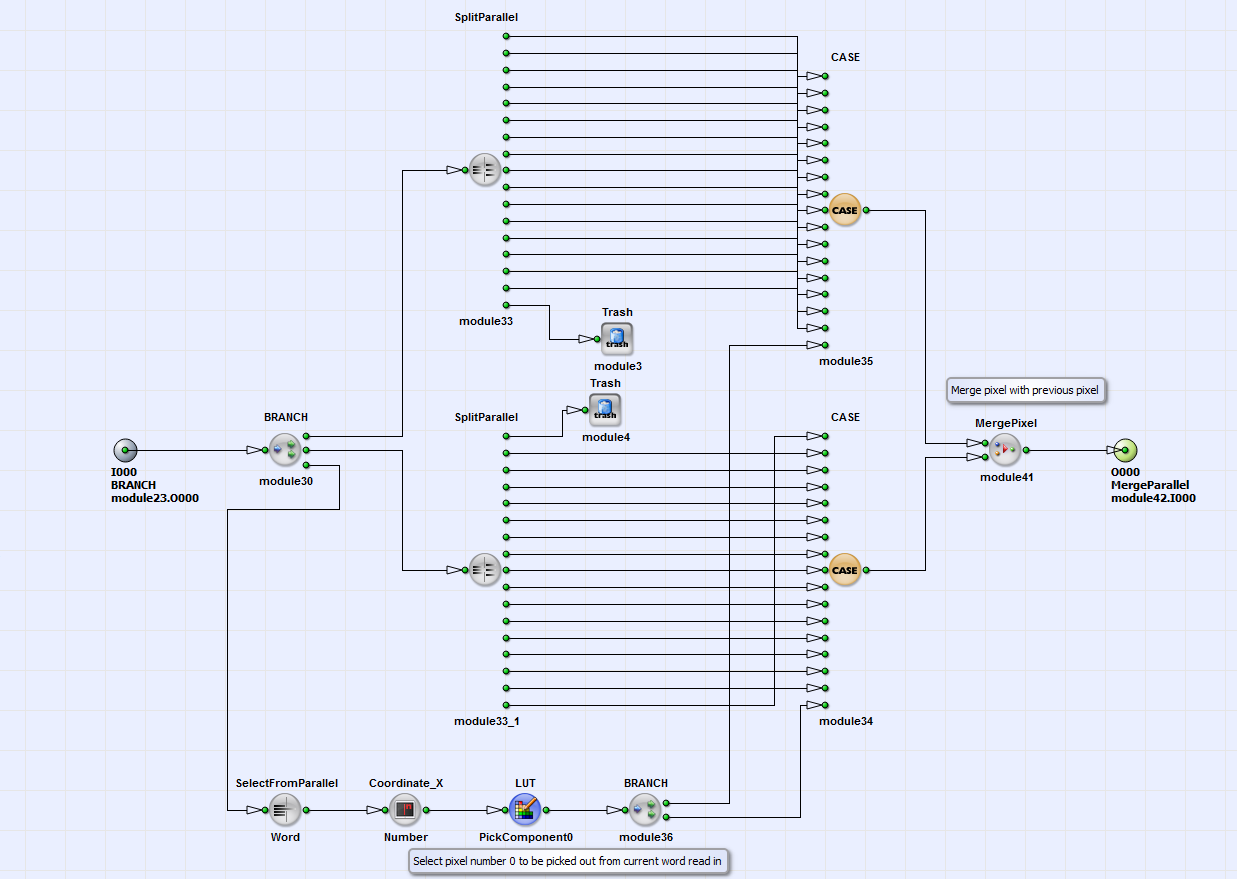
In Fig. 337 the content of the HierarchicalBox Pick_0 is shown. The lookup table PickComponent0 defines which pixel of a word read (SelectFromParallel: Word and Coordinate_X: Number) is the 0. component of the current output word. With the operator CASE the corresponding pixel is selected. Together with its predecessor it is written to the current pixel (MergePixel). Analog to this procedure described, the pixels 1 to 15 (or 7 with parallelism 8) of the current output word are selected with the modules Pick_1 to Pick_15 (or to Pick_7). Die single pixels Pick_0 to Pick_15 (or to Pick_7) are combined to the current transformed/scaled word with parallelism 16 or 8 (MergeParallel in Fig. 336).
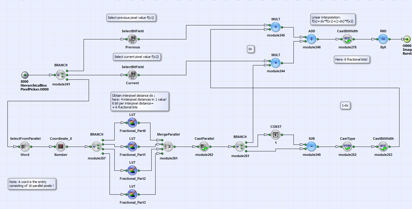
In order to obtain the correct value on the pixel positions in the output image sent to PC, the interpixel position in the source image has to be considered. In the module Interpolation (Fig. 334) a linear interpolation is performed [Bur06]:

Here  is the pixel value in the output image,
which corresponds to value
is the pixel value in the output image,
which corresponds to value  in the source image
at position x. Furthermore
in the source image
at position x. Furthermore  and
and
 are the values at pixel coordinates
 and
and
 in the source image. The interpixel position is
 . More information on linear interpolation you
can find e.g. in [Bur06].
. More information on linear interpolation you
can find e.g. in [Bur06].
The content of the module Interpolation is shown in Fig. 338.
The values of current pixels  and their
predecessors
and their
predecessors  are separated with the operators
SelectBitField: Current and SelectBitField: Previous. The values of
are separated with the operators
SelectBitField: Current and SelectBitField: Previous. The values of
 and
and
 are multiplied with
 and
and
 according to eq.
30. The information for the interpixel position
according to eq.
30. The information for the interpixel position
 is contained in four lookup tables
Fractional_Part0 to Fractional_Part3 in the design “ScalingLineP16.va”. Every table contains for 4 pixels of the
current output word the interpixel position
is contained in four lookup tables
Fractional_Part0 to Fractional_Part3 in the design “ScalingLineP16.va”. Every table contains for 4 pixels of the
current output word the interpixel position  .
Every interpixel position has 6 bit depth. The content of the LUTs Fractional_Part0 to Fractional_Part3 can be
created with the external C++ program „ScalingLUTS.cpp” or alternative with the MATLAB modules “LUTS_Scaling.m” and
“ScalingTablelLine.m”. See therefor also
section in this document.
The design “ScalingLineP8.va” has one table Fractional containing the interpixel
position. Its content can also be created with the external C++ and Matlab program modules.
Finally the transformed/scaled line image is sent via DMA transfer to PC (see Fig. 334).
.
Every interpixel position has 6 bit depth. The content of the LUTs Fractional_Part0 to Fractional_Part3 can be
created with the external C++ program „ScalingLUTS.cpp” or alternative with the MATLAB modules “LUTS_Scaling.m” and
“ScalingTablelLine.m”. See therefor also
section in this document.
The design “ScalingLineP8.va” has one table Fractional containing the interpixel
position. Its content can also be created with the external C++ and Matlab program modules.
Finally the transformed/scaled line image is sent via DMA transfer to PC (see Fig. 334).
The lookup tables necessary for the design “ScalingLineP16.va” and “ScalingLineP8.va” (see section ) can be created either with the C++ program “ScalingLUTs.cpp” (in folder “LUTS_Cpp”) or with the MATLAB program modules “LUTS_Scaling.m” and “ScalingTableLine.m”(in folder “LUTS_MATLAB”).
1. Please define following parameters in the program (or in the command prompt):
//////////////////////Parameter////////////////////
/ Please specify these parameters!//////////
uint64_t parallelism = 8; // =8 for "ScalingLineP8.va" and =16 for "ScalingLineP16.va"
uint64_t fractionalBits = 6; // = 6: default value in "ScalingLineP8.va" and "ScalingLineP16.va"
uint64_t noOfFractionalLUTs = parallelism == 8 ? 1 : 4; // number of fractional tables = 1 in "ScalingLineP8.va" and
= 4 in "ScalingLineP16.va"
int InputWidth; // width of input image
int OutputWidth; // width of image sent to PC
For the VisualApplets design “ScalingLineP16.va” set the parallelism parameter to 16 and for“ScalingLineP8.va” to 8. The number of fractionalBits of 6 is a default value in both designs. The design “ScalingLineP16.va”has four tables (const int noOfFractionalLUTs = 4) containing the interpixel positions for the interpolation (see Fig. 338). The design “ScalingLineP8.va” has one table (const int noOfFractionalLUTs = 1) instead. The scaling of your line image is defined by the relation between InputWidth and OutputWidth.
2. Run the program!
3. Following files are created which can be loaded to the lookup tables in the VisualApplets designs:
| File | VA LUT |
|---|---|
| FractionalTable_0.txt to FractionalTable_3.txt | Fractional_Part0 (or Fractional for parallelism 8) to FractionalPart_3 |
| PickerTable_0.txt to PickerTable_15.txt (or to PickerTable_7.txt) | PickComponent0 to PickComponent15 (or to PickComponent7) |
| TableWordsToRead.txt | WordsToRead |
| RemoveTable.txt | RemovePixel |
Table 25. Files and their corresponding lookup tables in Visual Applets
In addition the text file ScalingTable.txt is created. It contains for every output image pixel the corresponding coordinates in the source image (see also section ).
Please open the module “ScalingTableLine.m” and define the parameters
InputWidth=…;
OutputWidth=…;
1. Run the program!
2.The text file ScalingTableLine.txt is created. It contains for every output image pixel the corresponding coordinates in the source image.
3. Please open the module “LUTS_Scaling.m” and define the parameters
parallelism = ...;
NoOfFractionalBits=...;
NoOfFractionalTables=...;
Run the program! The files created correspond to the files in Tab. 25 which can be loaded to the lookup tables in the VisualApplets designs.
